Contents
Raphael Horvath1), Max Stammet1) Sylvain Petitgirard2), Ashkan Salamat3)
1) IRsweep AG, Laubisrütistr. 44, 8712 Stäfa, Switzerland
2) ETH Zurich, Inst. für Geochemie und Petrologie, Sonneggstrasse 5, 8092 Zürich, Switzerland
3) Department of Physics & Astronomy & HiPSEC, University of Nevada Las Vegas, Las Vegas, Nevada 89154, United States
The IRis-F1 is a laser-based instrument whose beam can be tightly focused, so it is well-suited to measuring small features. This application note shows how the IRis-F1 can be used to perform microscopy.
In a standard optical microscope, the smallest resolvable feature (d) is defined by the numerical aperture of the focusing optic (NA) and the wavelength of light used (λ), according to the Abbe diffraction limit:
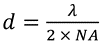
The NA used in the present setup is 0.5 and the wavelength is 6 µm. This means the diffraction limited resolution is also 6 µm. In contrast to this theoretical limit, the example shown here uses a rather simple optical setup which gives a spatial resolution of approximately 15 µm.
Experimental setup
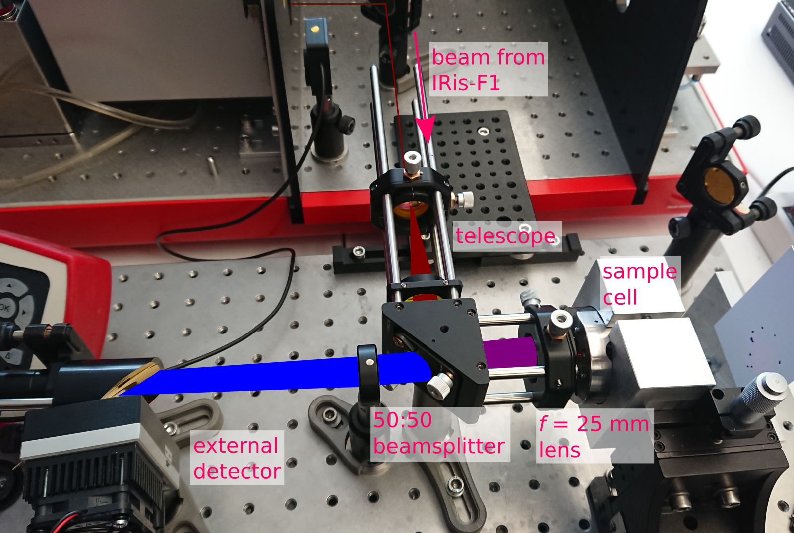
Figure 1. Picture of the experimental setup. The telescope expands the beam which is focused on a sample by a 25 mm focal length lens. The reflected radiation is re-collimated by the same lens. A beamsplitter allows for the incident and returned radiation to take the same path.
The setup is shown in Figure 1. First, the collimated beam is expanded to a diameter of ca. 12 mm with a Galilean telescope. The expanded beam is then directed towards the sample using a beamsplitter. This way, the same 25 mm lens can be used to focus the beam on the sample and re-collimate the reflection from the sample. A notable downside to this approach is that approximately 75% of the light is lost due to the beamsplitter. However, the powerful source of the IRis-F1 compensates for this, and even here the beam has to be attenuated to avoid saturating the detector.
For this experiment, we mapped the inside of a spectroscopic sample with a laser module centered at 1650 cm-1. In this cell, there are three samples which are surrounded by a metallic gasket. The diameter of the entire assembly is ca. 400 µm. The scan was done in steps of 10 µm, and 41 scans were taken in each of the x and y dimensions. Figure 2 shows the result.
Results
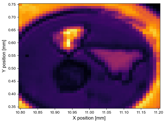
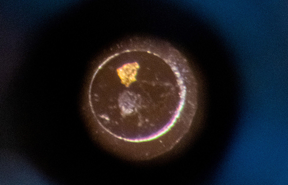
Figure 2. (left) Infrared map of the cell, with focus on the spectral line at 1640 cm-1. (right) A visible image of the same cell taken with an optical microscope.
From Figure 2, it is clear that there are three targets, and each of them possesses a different reflectivity. In the visible (right), the bright spot at the top is gold, the triangular feature on the right is a flake of graphite and the dark spot is a sample of MoS2. The infrared data were referenced against the gold flake and the displayed intensity was extracted at 1640 cm-1 and normalized. However, each point contains the full spectral information from 1620-1680 cm-1, if needed.
Conclusions
There are several reasons why it is advantageous to use an IRis-F1 for microscopy and mapping applications. Each spot can be acquired in approximately 1 ms, with a point-to-point acquisition delay of ca. 4 ms. This means that by automating the mapping, an image like the above can be produced in less than 10 seconds. Furthermore, the full 1 µs time resolution of the IRis-F1 can be used to monitor dynamic processes at every point on the sample. For example, studying the photoexcitation processes of low sample volumes or distinguishing different regions in heterogeneously mixed samples becomes a possibility.
Finally, the spectral resolution shown here was limited by the optics available in-house. With a more complex optical setup, we expect future results to push much closer to the diffraction limit.
Related products
IRis-C
The IRis-C is the next generation instrument in IRsweep’s quantum cascade laser frequency comb spectrometer line. It uses the same dual-comb spectroscopy technology as IRsweep’s IRis-F1, offering microsecond time-resolution, high spectral resolution, and high optical brightness in the mid-infrared. With a substantial reduction in physical dimensions and price, it is easily adaptable to any type of application and fits even tighter budgets.
IRis-F1
The IRis-F1 spectrometer offers you an unmatched combination of speed, brightness and multi-color measurements. The quantum cascade laser frequency comb spectrometer is the first turn-key frequency comb spectroscopy system. As opposed to single-frequency operation, which necessitates tuning over your spectral range of interest, you will achieve a broad spectral coverage in a single-shot measurement.
IRis-core
The IRis-core is an ideal basis for the setup of such a system in the mid-IR range: It offers two overlapping free-running QCL-based frequency comb lasers in a single system. The system outputs already co-aligned beams and comes with a set of drive instructions with factory-characterized heterodyning conditions. The system comes complete with drive electronics and a control computer with a graphical user interface.